Knowledge about Dew Point Analyzers, Oxygen Analyzers, Oxygen Sensors, Pirani Gauges & Thin Film Deposition
How to choose the dew point analyzer (https://www.avcray.com/products/moisture-analyzer/ )? What is the difference between online and portable?
In dew point measurement, mirror pollution is a prominent problem, and its impact is mainly manifested in two aspects; one is the Raoul effect, the second is to change the level of specular background radiation. The Raoul effect is caused by water-soluble substances. in case
This substance is carried in the test gas
(Generally soluble salts)
The mirror surface dew in advance, which will cause the measurement result to be positively biased
difference. If the pollutants are water-insoluble particles, such as dust, etc., the background scattering level will be increased and the photoelectricity will be increased.
The dew point analyzerhas zero drift. In addition, some substances with a lower boiling point than water are liable to condense
It is self-evident that the vapor (such as organic matter) will interfere with the measurement of the dew point. Therefore, no matter what type of dewpoint meter should be used to prevent contamination of the mirror. Generally speaking, the impact of industrial process gas analysis pollution is more serious. But even in the measurement of pure gas, the pollution of the mirror surface will accumulate over time. The selection of dew point instrument measurement conditions In the design of the dew point instrument, various factors that directly affect the heat and mass exchange in the dew condensation process must be considered. This principle is also applicable to the selection of the dew point device operating conditions with less automation.
Here we mainly discuss the problem of mirror cooling rate and sample gas velocity.
- The temperature of the measured gas is usually room temperature. So when the airflow passes through the dew point chamber
Time must affect the heat and mass transfer process of the system. When other conditions are fixed, increasing the flow rate will help the airflow and
Mass transfer between mirrors. Especially during low frost point measurement, the flow rate should be appropriately increased to speed up the formation of dew layer
Temperature, but the flow rate should not be too large, otherwise it will cause overheating problems. This pair of thermoelectric cooling dew points with relatively low cooling power
The instrument is especially obvious. Too much flow rate will also cause the dew point chamber pressure to decrease, and the change of flow rate will affect the thermal equilibrium of the system. Therefore, it is necessary to select an appropriate flow rate in the dew point measurement. The choice of the flow rate should depend on the cooling method and the structure of the dew point chamber. The general flow rate range is between 0.4 ~ 0.7Lmin-1. In order to reduce the influence of heat transfer, pre-cooling treatment can be considered before the measured gas enters the dew point chamber.
2.The speed of mirror cooling in dew point measurement
Control is an important issue. For automatic photoelectric dew point meters, it is determined by design, and for manual control of cold dew,
Point meter is a problem in operation. Because the cooling point of the cold source, the temperature measurement point and the heat conduction between the mirror surface have a process and
There is a certain temperature gradient. Therefore, thermal inertia will affect the process and speed of dew (frost), which will cause errors in measurement results.
difference. This situation also varies with the temperature measuring element used. For example, due to the structural relationship, the
The temperature gradient between the measuring point and the mirror is relatively large, and the heat conduction speed is relatively slow, which makes temperature measurement and condensation impossible.
Synchronization. In addition, the thickness of the exposed layer cannot be controlled. This will produce a negative error for visual inspection.
- Another problem is that cooling too fast may cause “overcooling”. We know that under certain conditions, water vapor reaches saturation
And state, the liquid phase still does not appear, or the water does not freeze when the temperature is below zero, this phenomenon is called supersaturation or “supercooling”
For the condensation (or frost) process, this phenomenon is often caused by the measured gas and mirror surface being very clean, or even a lack of a sufficient number of condensation cores. Suomi found in experiments that if a highly polished mirror surface And its cleanliness meets chemical requirements, the dew formation temperature is a few degrees lower than the actual dew point temperature. The supercooling phenomenon is short-lived, and the total time is related to the dew point or frost point temperature. This phenomenon can be observed through a microscope. One of the solutions is to repeat the operation of heating and cooling the mirror surface until this phenomenon is eliminated. Another solution is to directly use the water vapor pressure data of the subcooled water. And this is done just as the relative humidity definition of the meteorological system is below zero Coincide.
The difference between online and portable:
The online dew point analyzeris installed at a destination and is always working. Portable dew point meter. Take it out when you need to measure it. Wherever you need it, carry it at any time. Small and portable, easy to carry. Spark has a FM750 portable dew point meter.
Common problems and precautions of dew point meter
Dew point analyzeris an instrument that can directly measure the dew point temperature. A mirror surface is cooled in the sample’s wet air until the dew drops (or ice crystals) appear on the mirror surface, and the average temperature of the mirror surface is measured, which is the dew (frost) point temperature. It has a high humidity measurement accuracy, but requires a mirror with a very smooth finish, a highly accurate temperature control system, and an optical detection system with very sensitive dew drops (ice crystals). The pipe that sucks in the sample air must be kept clean during use, otherwise the impurities in the pipe will absorb or release moisture and cause measurement errors.
- How long does the instrument require calibration and maintenance?
Generally, it is recommended that the user check it once every two years, and once every six months in special cases (when the air pollution is severe).
- The instrument stagnates during the measurement and then the data decreases. Why?
This is the sensor performing the gain return function, which is to return to the previous test process for verification. At this time, the interface data is not moving, but the CPU is processing the data, so the data will drop immediately after a while.
- How to protect the sensor?
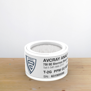
The built-in sensor of this instrument is protected by a probe protection chamber. When the protection chamber is running, it is automatically closed by a detector to make the instrument in a measurement state. Otherwise, it is automatically protected when the power is turned off.
Notes for use:
- The measuring instrument should be placed in a safe place to prevent damage. Avoid severe vibration.
- Do not measure corrosive gas.
- The probe should be cleaned and calibrated after a certain period of use, and the calibration interval is one year. When calibration is required, contact the manufacturer.
- When adjusting the gas flow rate, the control needle valve should be opened slowly so that the flow rate indicator is between 0.5-0.6
Liters / minute. If the flow rate exceeds 1 liter / minute, the flow rate display on the LCD indicates that the flow rate has exceeded the limit. At this time, the flow rate should be reduced to the specified value. (Excessive flow will damage the electronic flow sensor).
Selection of oxygen analyzer for glove box
Selection of special oxygen analyzers for glove boxes. There are many types of special oxygen analyzers for glove boxes independently developed and manufactured by Chengdu Jiuyin Technology. So how to choose? This article will tell you the characteristics and parameters of the special oxygen analyzer for the glove box to help you choose: small and beautiful appearance, all stainless steel shell; KF40 flange installation, easy installation; fast response speed, high measurement accuracy, long calibration cycle; Does not consume life, the transmitter has a built-in sensor automatic protection function, automatically shut down when the sample gas concentration is too high; high-precision temperature and pressure automatic compensation system to eliminate the error caused by the ambient temperature and pressure on the measurement accuracy; with display The user can use it intuitively and conveniently; the meter can test both trace oxygen in nitrogen and trace oxygen in argon. It can be used for glove box, and also can be used for on-line analysis of trace oxygen in mixed atmosphere of oxygen, nitrogen and inert gas, such as air separation and protective atmosphere furnace.
Precautions for using the oxygen analyzer
Precautions for use
Radon oxygen analysis instruments are generally divided into three categories according to different principles: fuel cell oxygen analyzers, zirconia sensor zirconia sensors, and magnetic oxygen analyzers. Oxygen analysis instruments have many precautions in use, otherwise problems of unequal analysis results are very easy to occur. Therefore, a few notes summarized by Laibai.com for your reference:
Before initial use, leak detection should be performed on connection points, solder joints, valves, etc. to ensure that oxygen in the air does not penetrate into the pipeline and the inside of the instrument, resulting in high measuremen t values.
- Before using the instrument again, purify the pipe system, blow out the leaked air, and ensure that there is no air leak when connecting the sampling pipeline.
- The change of the oxygen content in the sample gas will be affected by the pipe material and surface roughness. Therefore, generally copper pipes or polished stainless steel pipes are used for the connecting pipes instead of plastic pipes and rubber pipes.
- During microanalysis, it is necessary to avoid contamination of sample gas by dead angles such as various fittings, valves, gauges, etc. Therefore, the gas path system must be simplified as much as possible, and dead angles of connecting parts must be small. Power to prevent the escape of dissolved oxygen and cause pollution. Water seals, oil seals and wax seals can be used to ensure data.
Test principle of dissolved oxygen analyzer
- Solubility depends on temperature, pressure and dissolved salts in water
Dissolved Oxygen Analyzer Measurement Principle The solubility of oxygen in water depends on temperature, pressure and the salts dissolved in the water. The sensing part of the dissolved oxygen analyzer is composed of a gold electrode (cathode) and a silver electrode (anode) and a chlorine * potassium or potassium hydroxide electrolyte. Oxygen diffuses into the electrolyte through the membrane and forms a measurement loop with the gold electrode and the silver electrode. When a polarized voltage of 0.6 ~ 0.8V is applied to the dissolved oxygen analyzer electrode, oxygen diffuses through the membrane, the cathode releases electrons, and the anode receives electrons to generate current. The entire reaction process is: anode Ag + Cl → AgCl + 2e- cathode O2 + 2H2O + 4e → 4OH- According to Faraday’s law: the current flowing through the electrode of the dissolved oxygen analyzer is proportional to the partial pressure of oxygen, and there is a linear relationship between the current and the oxygen concentration under the condition of constant temperature.
Second, the representation method
Dissolved oxygen content is expressed in three different ways: oxygen partial pressure (mmHg); percent saturation (%); oxygen concentration (mg / L or 10-6). These three methods are essentially It’s no different.
(1) Partial pressure representation: The oxygen partial pressure representation is the basic and essential representation. According to Henry’s law, P = (Po2 + P H2O) × 0.209, where P is the total pressure; Po2 is the partial pressure of oxygen (mmHg); P H2O is the partial pressure of water vapor; 0.209 is the content of oxygen in the air.
(2) Percent saturation expression: Due to the complexity of aeration fermentation, the oxygen partial pressure cannot be calculated. In this case, the expression of percentage saturation is suitable. For example, if the dissolved oxygen is set to 100% during calibration and 0% at zero oxygen, the dissolved oxygen content during the reaction will be the percentage during calibration.
(3) Expression of oxygen concentration: According to Henry’s law, it can be known that the oxygen concentration is proportional to its partial pressure, that is: C = Po2 × a, where C is the oxygen concentration (mg / L); Po2 is the partial oxygen pressure (mmHg); Solubility coefficient (mg / mmHg · L). The solubility coefficient a is not only related to temperature, but also to the composition of the solution. For an aqueous solution with a constant temperature, a is constant and the oxygen concentration can be measured. The expression of oxygen concentration is not commonly used in the fermentation industry, but it is expressed in the process of sewage treatment and domestic drinking water.
Application of trace oxygen analyzer in glove box
The glove box is a laboratory equipment that fills the box with high-purity inert gas and filters out the active substances in the box. Also called vacuum glove box, inert gas protection box, etc. The glove box is a universal work platform that provides a very high purity inert gas environment. The inert gas concentration in this work platform can reach a very high level. Some materials, processes or experiments that are sensitive to water or oxygen can be used in the glove box. Made it happen. The main function is to remove O2, H2O and organic gases. Therefore, it is widely used in water-free, oxygen-free, dust-free ultra-pure environments, such as: lithium-ion batteries and materials, semiconductors, super capacitors, special lamps, laser welding, brazing, material synthesis, OLED, MOCVD, etc. Also includes biological applications, such as anaerobic bacteria culture, cell hypoxia culture and so on. This article mainly describes the application of trace oxygen analyzers in glove boxes.
Glove boxes have been increasingly used in scientific experiments, new material research and development, biomedicine, chemicals, lithium batteries, solar cells, nuclear materials and nuclear industry, new lighting, special welding, vacuum coating and other industries and fields. As a universal platform, the glove box can provide working conditions for experiments or production in high purity inert gas protection, low water and low oxygen content or dust-free aseptic environment.
Application of trace oxygen analyzer products in glove box of lithium battery industry
- Install the trace oxygen analyzer in the glove box: it is used to monitor the oxygen content in the box, and the current content can be displayed on the touch screen;
- It can realize the interlocking of the trace oxygen analyzer with the circulating fan and the purifier in the glove box, and can continuously remove oxygen when the oxygen content is high, and maintain the test or production conditions;
3. When the micro oxygen analyzer is regenerating in the purification system of the glove box, monitor the oxygen content in the box. Purify the oxygen content in the box within 24 hours. If the content is too high, you may suspect that the glove box is not tightly sealed or there are other problems;
4. The upper and lower limit alarm points of the oxygen content of the gas to be measured can be arbitrarily set according to the requirements of the on-site process.
- It can be used to monitor the increase of oxygen content caused by switching the transition chamber during the discharging and feeding process.
Application of Oxygen sensor in glove box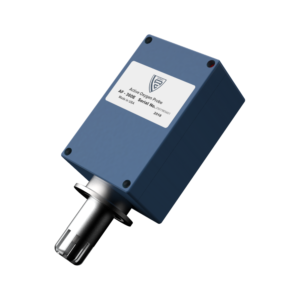
A glove box is a laboratory device that fills a tank with a high-purity inert gas and circulates active materials therein. The main function is to remove O2, H2O and organic gases. Some materials that are very sensitive to water or oxygen can be processed in the glove box. The glove box is a universal work platform that provides a very high purity inert gas environment. The concentration of inert gas in the working platform can reach very high levels. Some materials that are very sensitive to water or oxygen can be processed in the glove box. can be realised.
Glove boxes are increasingly used in scientific experiments. , New material development, biomedicine, chemicals, lithium batteries, solar cells, nuclear materials and nuclear industry, new lighting, special welding, vacuum coating and other industries and fields. As a universal platform, glove boxes provide working conditions that require experiments or production in high purity inert gas protection, low water and oxygen content, or dust-free aseptic environments. A trace oxygen sensor analyzer is required in the glove box. For details, please see the following:
- Install a trace oxygen sensor analyzer in the glove box: used to monitor the oxygen content in the cabinet and display the current content on the touch screen;
- The trace oxygen sensor analyzer can be interlocked with the circulating fan and purifier in the glove box to achieve continuous oxygen exhaust and maintain test or production conditions when the oxygen content is high;
- When the miniature oxygen meter is regenerated in the glove box purification system, monitor the oxygen content in the box. After 24 hours of purification, the oxygen content in the box should be less than 1 PPM. If the content is high, it may be suspected that the glove box is tightly sealed or other problems exist;
- The upper and lower alarm points of the oxygen content of the gas to be measured can be arbitrarily set according to the site process requirements.
- It can be used to monitor the increase in oxygen content caused by switching the transition chamber during feeding.
OFweek Mall analyzes the principle of trace oxygen sensor analyzer:
Electrochemical principle
High measurement accuracy, stable work, low price, short battery life, often using standard gas calibration, high maintenance costs. It can overcome the interference of acid gases, but it is not resistant to long-term corrosion of hydrogen fluoride / hydrofluoric acid.
- Principle of zirconia (such as ADEV):
High measurement accuracy, stable operation, high price, long sensor life and maintenance-free. It can overcome the interference of acid gases and is resistant to hydrogen fluoride / hydrofluoric acid corrosion.
2.1 The electrode is added with a special protective layer during the coating process, which greatly improves the electrode’s corrosion resistance, overcomes the interference of acid gases, and resists hydrogen fluoride / hydrofluoric acid corrosion;
2.2 The core component of the zirconia oxygen analyzer-zirconia component, adopts a unique formula and advanced molding technology to make its measurement accuracy and service life;
OFweek Mall’s recommended micro oxygen sensor is Southland’s EMD-485. This micro oxygen sensor has very high accuracy, 0-10ppm level, and the measurement results are relatively accurate.
Pirani vacuum gaugerepair
The maintenance of Pirani pressure gauges has entered the 11th Five-Year Period. China’s instruments and meters have entered a rapid development stage. The scale of the industry has continued to expand, and the product variety has become more complete. It has achieved an average annual ultra-high-speed increase of 20%, and its profit margin has also shown rapid growth. Although the global financial crisis in 2008 had a certain impact on the development of China’s instrumentation industry, the import and export deficit exceeded 10 billion US dollars. However, the compound growth rate of China’s instrumentation industry in 2009 reached 8.88%, and in 2010 it achieved a total industrial output value of 808.5 billion yuan.
The development of instruments and meters during the 11th Five-Year Plan period is mainly due to the rapid development of China’s national economy. With the deepening of the integration of the two industries, instrumentation has brought great market demand and development space. In addition, China’s instrumentation industry has significantly improved its own technological level, its market share has continued to increase, and the strength of local enterprises has begun to emerge, which has also promoted the rapid development of the instrumentation industry.
Whether the excitation power switch is closed. You can also check the current excitation voltage feedback in r016. 4. F006 Overvoltage fault countermeasures: Use a multimeter to check whether there is overvoltage in the main circuit incoming line voltage. 5. F007 Undervoltage fault countermeasures: Use a multimeter to check whether the main circuit incoming line voltage is undervoltage. If it is normal to check whether the fast-melt is blown, K03 is energized. If there is a fuse in the fast-acting fuse, be sure to check the thyristor first to see if there is any damage to the thyristor. After replacing the new fast-acting fuse or thyristor, you must perform a thyristor self-test with P830 = 3. 7. F035 drive stalled countermeasures: check the motor running condition, whether there is a stalled phenomenon. 8. F038 overspeed countermeasures: check whether the encoder wiring is normal, and also check whether the excitation circuit is normal. Sometimes, the 1C1D1 feedback line is reversed and the F38 phenomenon will occur. 9. F040 is in the fault state.
Avcray.com is a professional industrial automation equipment and its circuit board maintenance organization. The company has advanced domestic testing equipment and testing instruments, an excellent team of engineers, and maintenance engineers with decades of experience. Various testing platforms provide a good guarantee for improving the repair rate.
Our maintenance is not restricted by brands, and the repair scope covers: semiconductor manufacturing equipment, industrial power supplies, inverters, PLCs, servo drives, servo motors, touch screens, displays, industrial circuit boards, equipment control circuit boards I ∕ O boards, elevator control boards, Air conditioning control circuit board, temperature controller, DC speed governor, forklift control circuit board, dryer circuit board, light box controller, proportional valve, laser stylus, high voltage test board, speed card, various instruments, switches Using high-frequency power supply, CPU main control board and other various instruments to repair the whole machine or local circuit boards, industrial control equipment control circuit boards in various industries can achieve chip-level maintenance, and the repair success rate is more than 90%.
Analysis of thin film deposition controller
The thin film deposition controller uses atomic layer deposition to prepare high-quality thin film materials. The precursor must meet good volatility, sufficient reactivity, and certain thermal stability. The precursor cannot have corrosion or dissolution on the film or substrate. The precursor pulses. Time needs to ensure single-layer saturation adsorption, and the deposition temperature should be kept in the window to avoid CVD growth caused by precursor condensation or thermal decomposition, which makes the film non-uniform.
After the dust-containing gas enters the hopper of the dust collector of the filter cartridge, due to the sudden expansion of the cross section of the airflow, a part of the coarse dust particles in the airflow settle under the force of gravity and inertia, and the fine-grained, low-density dust particles enter the filter cartridge to collect dust. After the filter chamber, through the combined effects of Brownian diffusion and sieving, dust is deposited on the surface of the filter material, and the purified gas enters the clean room and is discharged by the exhaust pipe through the fan.
When the pulse valve is opened, the compressed air in the air bag ejects a high-speed, high-pressure ejection airflow through the orifice in the blow pipe through the pulse valve, thereby forming an induction equivalent to 1 to 2 times the volume of the ejection airflow. The defect flow enters the dust filter cartridge together, and the thin film deposition controller causes instantaneous positive pressure in the dust filter cartridge to cause bulging and fretting; the dust deposited on the filter material falls off and falls into the ash bucket, and the dust in the ash bucket Continuous discharge through the unloader. Some large particles, high-density dust and condensed dust particles in the air flow spin down the ash bucket along the wall of the cylinder under the action of centrifugal force and gravity. The fine dust particles with small particle size and small density are suspended in the gas and passed through the air flow distribution device to enter uniformly. The filter chamber is dispersed in the gap of the filter bag, and is deposited on the surface of the filter bag through the inertia collision of the surface of the filter bag, sieving, and the like, and the purification gas is discharged by the main fan.
Popularization of relevant knowledge of thin film deposition controller
The thin film deposition controller includes a reaction chamber, and further includes at least two sets of film forming mechanisms, the at least two sets of film forming mechanisms respectively corresponding to at least two film forming regions of a substrate to be formed; each set of the film forming mechanisms is configured to A film-forming environment is formed in the reaction chamber, and at least one of the process parameters in the film-forming environment formed by each set of the film-forming mechanisms is different, so as to form thin films with different properties or film parameters in the corresponding film-forming regions. film.
Combined with high-speed processing and a large number of processing time and cost savings, the improvement of parts has become an important factor. In film processing, in order to obtain benefits, it is necessary to choose a suitable surface treatment process. For heavy-duty machinery, CVD high-temperature titanium plating should be selected and supplemented with precision vacuum heat treatment to achieve acceptable deformation.
真空 Background vacuum of film deposition chamber: ≤1Pa;
Thin film deposition chamber: composed of stainless steel bottom and glass bell cover; effective size: Φ220 × H230mm;
RF coupling method: capacitive coupling / inductive coupling; RF source power: with 500W13.56MHz;
Gas system: controlled by three rotor flowmeters (optional mass flowmeter);
Substrate heating temperature: controllable from room temperature to 300 ° C;
Parallel plate electrode: Φ70mm;
Working reaction gas: uniformly introduced from the micro-holes on the electrode plate;
Vacuum extraction system: 2XZ-4 rotary vane mechanical pump, 4L / S, single-phase 220V AC power supply;
Pipes and valves: stainless steel and metal bellows
报警 Alarm the abnormal situation such as over-current, over-voltage and open circuit, and implement corresponding protective measures;
Power supply: AC220V, 50Hz, power of the whole machine is 2KW.
Operation and processing cost is an important issue to be considered in the process design of thin film deposition controller. Generally, the production technology of thin film is used as the core technology.
The management staff lacks knowledge of the equipment, so the designed processing system is as easy to operate and maintain as possible.
It must be ensured that the quality of the water produced by the adopted process meets the standards for reuse of thin film equipment.
What maintenance work is needed for the thin film deposition controller
The thin film deposition controller establishes a temperature measurement thin film control system on the basis of modularity, which can support expansion of 4 input and output ports and probes, real-time frequency-temperature curve and 500 ° C operation crystal. The instrument is equipped with a quick setting menu, 6 context-sensitive buttons, and a simple parameter setting knob, which is easy to set up and operate. It is used to develop, test and download procedures, and to record the instrument data to a PC. Process control of process analysis and quality control program, especially suitable for low deposition rate, measurement rate is 10 readings per second, storage capacity can reach 100 processes, 1000 layers of film, 50 kinds of film materials.
When the operating temperature exceeds 1600F / 710C, measurement cannot be performed, otherwise the instrument will be damaged. When the ambient temperature is lower than 00C, the PH electrode may be damaged. Be careful not to exceed the specified temperature range. Store the instrument near a heat source or in the weather. In hot conditions, the temperature can easily reach or exceed 1500F, which will cause the instrument to measure incorrectly.
Electrode replacement electrode model, confirm the thin film deposition controller model and serial number to ensure the correct electrode model is selected, each instrument is equipped with a corresponding electrode model.
Electrode cleaning conductance / TDS / resistance conductance cells should be kept as clean as possible. Rinse the electrode cells with a sufficient amount of clean water to prevent debris from accumulating on the electrodes. Precipitation forms a thin film, which reduces the degree of testing. Once an oil film is formed or dirt is deposited on the electrode, it is washed with a common non-corrosive cleaning agent and rinsed with water to accurately test.
Battery replacement: Dry the surface of the instrument, unscrew the four screws at the back, carefully open the back cover, remove the back cover, remove the battery, and replace it with a new 9V alkaline battery, cover the back cover, and tighten the screws. Because non-erasable readable memory is installed, the recorded data and correction change settings stored in the memory will not disappear even if the power is turned off or the battery is being replaced.
